Timing Analysis of Paths Part - II
In our previous discussion,
Timing Path Analysis Part I, we have seen timing path analysis of Reg-to-Reg
timing path and we put our discussion on hold for other paths. We are going to
analyse other paths and understand the meaning of input external delay and
output external delay.
So, what are these
delays???
Input External Delay
The input external delay component comes in In-to-Reg timing path analysis. It is delay comes from another block to our working block. Refer to the figure below.
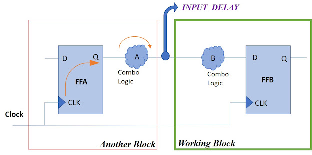 |
| Figure 1: Input Delay |
While analysing In-to-Reg
timing path, we consider such inter-block situation to be like Reg-to-Reg
timing path.
Input External delay is
the summation of delay of CLK-Q delay of Flip Flop A and Combinational
logic A (Shown in the figure 1)
Consider the Reg-to-Reg
timing path, where FFA is lunch Flip Flop and FFB capture Flip Flop. Here, we
are trying to get the input delay component in this timing path.
Take Setup analysis
formula:
RT – AT = [Clock
Period - Setup Time of FFB] – [ (CLK-Q) delay of FFA + Combo A
+ Combo B]
RT – AT = Clock
Period - Setup Time of FFB – (CLK-Q) delay of FFA – Combo A – Combo B
Here, (CLK-Q) delay of FFA + Combo A
= Input External Delay = Input Delay. This delay doesn’t
belong to our block but we have to add in our calculation because input delay
is going to contribute in our block.
Output External Delay
The output external delay component comes in Reg-to-Out timing path analysis. It is delay goes to another block from our working block. Refer to the figure below.
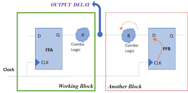 |
| Figure 2: Output Delay |
While analysing
Reg-to-Out timing path, we consider such inter-block situation to be like
Reg-to-Reg timing path.
Output External delay is
the summation of delay of Combo B delay and Setup Time of Flip Flop B
(Shown in the figure 2)
Consider the Reg-to-Reg
timing path, where FFA is lunch Flip Flop and FFB capture Flip Flop. Here, we
are trying to get the output delay component in this timing path.
Take Setup analysis
formula:
RT – AT = [Clock
Period - Setup
Time of FFB] – [ (CLK-Q) delay of FFA + Combo A + Combo B]
RT – AT = Clock
Period - Setup
Time of FFB – (CLK-Q) delay of FFA – Combo A – Combo
B
Here, Combo B + Setup Time of FFB =
Output External Delay = Output Delay. This delay doesn’t
belong to our block. That’s why we have to remove always from our delay
calculation.
Consider the following
data for analysis: Unit in ns
Combo Delay: Min =
0.2 and Max = 0.7
CLK-Q Delay : Min =
0.3 and Max = 0.7
Input Delay: Min = 0.4 and Max = 1
Output Delay: Min =
0.4 and Max = 1
Setup Time and Hold Time
= 0.3
Time Period = 2
IN-TO-REG TIMING PATH
ANALYSIS
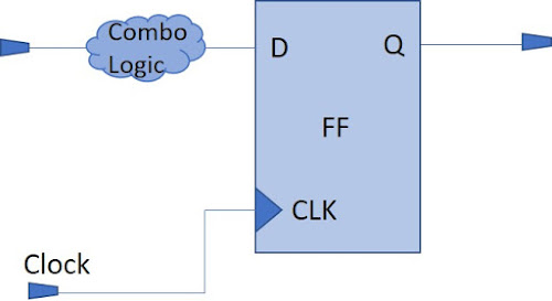 |
| Figure: In-to-Reg Timing Path |
Setup Analysis
AT = Input Delay MAX
+ Combo Delay MAX
AT = 1 + 0.7
AT = 1.7
RT = T – Setup Time of FF
RT = 2 – 0.3
RT = 1.7
Setup Analysis = RT – AT
= 1.7 – 1.7 = 0 (MET)
 |
| Figure: Setup Analysis of In-to-Reg Timing Path |
Hold Analysis
AT = Input Delay MIN
+ Combo Delay MIN
AT = 0.4 + 0.2
AT = 0.6
RT = Hold Time FF
RT = 0.3
Hold Analysis = AT – RT =
0.6 – 0.3 = 0.3 (MET)
 |
| Figure: Hold Analysis of In-to-Reg Timing Path |
REG-TO-OUT TIMING PATH
ANALYSIS
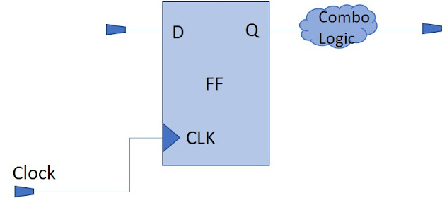 |
| Figure: Reg-to-Out Timing Path |
Setup Analysis
AT = CLK-Q Delay MAX
+ Combo Delay MAX
AT = 0.7 + 0.7
AT = 1.4
RT = T – Setup Time of FF – Output Delay Max
RT = 2 – 0.3 – 1
RT = 0.7
Setup Analysis = RT – AT = 0.7 – 1.4 = - 0.7 (VIOLATED)
 |
| Figure: Setup Analysis of Reg-to-Out Timing Path |
Hold Analysis
AT = CLK-Q Delay MIN
+ Combo Delay MIN
AT = 0.3 + 0.2
AT = 0.5
RT = Hold Time of FF –
Output Delay MIN
RT = 0.3 – 0.4
RT = - 0.1
Hold Analysis = AT – RT = 0.5 – (-0.1) = 0.6 (MET)
 |
| Figure: Hold Analysis of Reg-to-Out Timing Path |
IN-TO-OUT TIMING PATH ANALYSIS
In-to-Out timing path is the
purely combinational path which consists of only combinational logic elements.
 |
| Figure: IN-to-Out Timing Path |
AT = Input DelayMAX
+ Combo_1MAX + Combo_2MAX
AT = 1 + 0.7 + 0.7
AT = 2.4
RT = Time – Output DelayMAX
RT = 2 – 1
RT = 1
Setup Analysis: RT – AT =
1 - 2.4 = -1.4 (VIOLATED)
 |
| Figure: Setup Analysis of In-to-Out Timing Path |
AT = Input DelayMIN
+ Combo_1MIN + Combo_2MIN
AT = 0.4 + 0.2 + 0.2
AT = 0.8
RT = – Output DelayMIN
RT = - 0.4
Hold Analysis: AT – RT =
0.8 – (-0.4) = 1.2 (MET)
 |
| Figure: Hold Analysis of In-to-Out Timing Path |
At this note of discussion, we wrapped up this topic and we will meet soon with a new topic of STA. Thank You. Have a nice day.


Comments
Post a Comment
If you any doubt, please let me know